

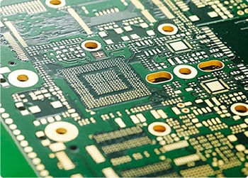
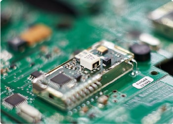
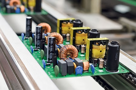










When you pick a substrate for an RF board, the decision usually comes down to one thing: can the material hold its electrical properties once frequency goes up. Cheap FR-4 blends drift. Rogers RT5870 laminate sits in the middle of the PTFE glass microfiber reinforced lineup, and that middle position is exactly why it keeps showing up in production designs. The RT5870 high frequency PCB ends up in microwave front ends, antenna feeds and radar modules where the dielectric has to stay honest across temperature swings.
The number engineers check first is Dk. RT5870 holds 2.33 ± 0.02 from 8 to 40 GHz. That bandwidth is wider than most designs actually need, but it means the part does not surprise you when you tune the stack-up. Temperature moves it very little — small phase drift, nothing that forces a redesign of the feed network. Loss tangent sits at 0.0012 at 10 GHz, low enough that power will not bleed off as heat before it reaches the antenna. For 5G feed lines and Ku-band links, that is the kind of number you can build a BOM around.
Dimensional behavior matters more once the board leaves the lab. Lamination, etch, drill — each step pulls at the material. Lower-cost PTFE boards sometimes warp after reflow or shrink unevenly across panels, and then your controlled-impedance lines are no longer controlled. RT5870 CTE is low enough that layer registration stays tight through all those steps. This is what makes the RT5870 high frequency printed circuit board viable for multi-layer builds where trace spacing and layer alignment are non-negotiable.
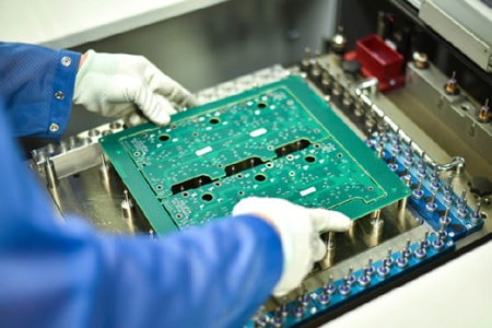
On the fab floor, RT5870 is not a diva. It runs through standard etch, plate and drill lines the same way other Rogers PTFE materials do. No special chemistry. No exotic prepreg handling. It also takes most process solvents without fuss, which keeps yield up. The reason custom high frequency PCB jobs pick it so often is simple: you get mid-tier electrical performance without the lead time and sticker shock of ultra-low-loss grades. Manufacturers do not have to retool, and buyers do not have to justify a premium material budget.
Outdoor use is where a lot of RF circuit boards quietly fall apart. Moisture uptake, thermal cycling, dust, vibration — the box keeps living on a rooftop or inside a roadside cabinet. RT5870 absorbs very little water and handles repeated temperature swings without its Dk drifting. Point-to-point radio units, automotive radar modules, industrial sensors: these are not lab benches, and they cannot be brought back in every winter. The RT5870 high frequency circuit board is chosen for those boxes because it keeps running after the spec temperature range has been tested a few hundred times.
It is not the right answer for every RF job. Above 40 GHz, when you are pushing into the higher mmWave bands and every tenth of a dB matters, you move up to a lower-loss Rogers grade. But for the bulk of commercial work between 2 GHz and 40 GHz, an RT5870 PCB covers the requirement without overpaying. Designers end up picking it because the performance is predictable and the cost line in the BOM stays reasonable.
If your project lands in that 2–40 GHz window, RT5870 is a reasonable default. The one thing worth doing early is talking to your board shop about stack-up and copper foil choice — rolled versus electrolytic changes surface roughness and therefore insertion loss. Get that sorted before you lock the layout, and the rest usually falls into place.