

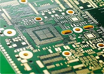
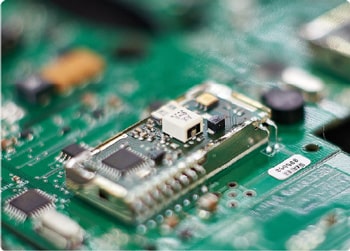
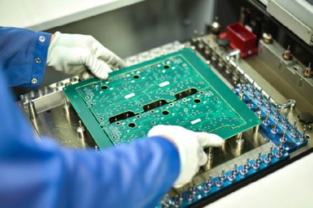
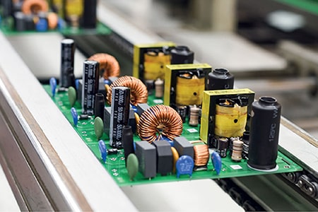










Millimeter wave radar serves as a core sensing component for automotive active safety systems and industrial precision detection devices. It operates on ultra-high frequency bands ranging from 24GHz to 77GHz, which imposes far stricter requirements on circuit board performance than conventional high-frequency hardware. Millimeter wave radar PCB must deliver steady signal transmission, minimal dielectric loss and reliable structural stability throughout long-term operation. Standard full FR4 boards struggle to suppress high-frequency attenuation and phase drift at these elevated frequencies. Pure Rogers high-frequency laminates perform well but carry prohibitive material and processing costs for mass production. This is why the RO4835+FR4 hybrid stackup has become the most balanced, widely adopted solution for commercial millimeter wave radar manufacturing.
Low high-frequency dielectric loss is the baseline standard for any qualified automotive 77GHz millimeter wave radar PCB. Millimeter wave signals are extremely sensitive to substrate material properties. Even minor dielectric loss can weaken signal strength, shorten effective detection range and cause inaccurate ranging data. FR4 laminates exhibit high, frequency-unstable Df values that worsen noticeably at millimeter wave bands. Rogers RO4835 tells a different story. It maintains a steady dissipation factor of 0.0037 from 10GHz up to 77GHz. This consistent low-loss characteristic stabilizes antenna signal transmission and protects the integrity of differential RF links in radar transceiver circuits.
Broadband dielectric stability directly defines long-term radar detection accuracy. Most common PCB substrates suffer obvious Dk deviation under ultra-high frequency working conditions. This triggers random impedance fluctuations and unwanted signal reflection, disrupting overall radar precision. RO4835 locks in a stable dielectric constant of 3.48 across all mainstream millimeter wave bands with tight tolerance margins. It eliminates frequency-related signal distortion entirely. Designers can complete highly accurate impedance matching with fewer corrective iterations, a critical advantage for reliable high-frequency mmWave radar sensor PCB operation.
The biggest engineering breakthrough for modern millimeter wave radar boards is the optimized RO4835 and FR4 mixed lamination stackup. Practical radar design separates circuit functions clearly. All RF antenna layers and high-speed transceiver signal traces are arranged on RO4835 high-frequency laminates to guarantee low-loss RF performance. Meanwhile, conventional power layers, ground planes and digital control circuits adopt cost-efficient FR4 material. This targeted layering method isolates sensitive high-frequency signal areas from ordinary digital circuits. It avoids unnecessary over-engineering and cuts wasted high-frequency substrate usage.
This hybrid stackup strikes a perfect balance between RF performance and mass production feasibility. Full RO4835 boards deliver exceptional high-frequency performance, yet their premium material cost and strict processing rules limit large-scale application. Pure FR4 stacks are affordable but cannot meet millimeter wave loss requirements. The RO4835+FR4 structure combines the best of both materials. It retains RO4835’s ultra-low loss and superior anti-oxidation capabilities for core radar signals. It also leverages FR4’s mature lamination process, forgiving process window and high batch yield. In actual mass production, this hybrid design reduces overall board costs by nearly 30%, making it ideal for high-volume radar module manufacturing.
Radar equipment always operates in harsh, dynamic working environments. High temperatures, continuous vibration and repeated thermal cycling easily degrade unoptimized PCB structures. RO4835 features a low thermal expansion rate and 10 times stronger oxidation resistance than standard high-frequency substrates. It effectively prevents common defects like layer delamination, micro via cracking and signal drift under thermal stress. When paired with rigid FR4 layers, the hybrid board maintains stable electrical and mechanical performance through thousands of temperature cycles. It significantly extends the service life of vehicle and industrial radar modules.
Process compatibility is another key advantage of custom RO4835+FR4 hybrid millimeter wave radar PCB. Many hybrid high-frequency boards suffer from resin overflow and layer misalignment due to CTE mismatch between different materials. RO4835 shows excellent structural compatibility with standard FR4 prepreg. With properly segmented lamination temperature and pressure control, manufacturers can completely avoid thermal mismatch defects. Finished boards feature flat surfaces, precise layer registration and consistent impedance values, fully satisfying the tight routing tolerances of compact high-density radar circuits.
This hybrid stackup solution covers nearly all mainstream millimeter wave radar applications on the market today. It is widely deployed in 24GHz industrial obstacle avoidance radar, 77GHz automotive long-range sensing radar, vehicle intelligent perception modules and miniaturized industrial millimeter-wave detection devices. For mid-to-high-end radar products that demand stable RF performance and controllable production costs, RO4835+FR4 hybrid lamination has become a universally recognized industry standard.
In short, professional millimeter wave radar PCB design is far more than simple material stacking. True product competitiveness relies on reasonable layer matching and precise high-frequency performance control. The RO4835+FR4 hybrid stackup design successfully resolves the long-standing industry trade-off between premium RF performance and affordable mass production. It remains the most reliable, process-friendly solution for modern commercial and industrial millimeter wave radar PCB manufacturing.
Rogers RO4835 Full Performance Specification Table
The table below covers verified industrial-grade parameters ofRO4835 high stability RF substrate. All typical values follow official Rogers datasheet standards and common ASTM/IPC test methods, supporting high-frequency PCB simulation, stackup design and mass production validation.
|
Parameter Category
|
Technical Property
|
Typical Value
|
Test Condition & Standard
|
Unit
|
|---|---|---|---|---|
|
Electrical Properties
|
Process Dielectric Constant (Dk)
|
3.48 ± 0.05
|
10GHz, 23℃
|
–
|
|
Design Dielectric Constant (Dk)
|
3.66
|
8GHz – 40GHz broadband
|
–
|
|
|
Dissipation Factor (Df)
|
0.0037
|
10GHz, 23℃
|
–
|
|
|
Thermal Coefficient of Dk (TCDk)
|
+50
|
-50℃ to 150℃
|
ppm/℃
|
|
|
Volume Resistivity
|
5×10⁸
|
ASTM D257, room temperature
|
MΩ·cm
|
|
|
Thermal Properties
|
Glass Transition Temperature (Tg)
|
280
|
DSC test
|
℃
|
|
Decomposition Temperature (Td)
|
390
|
TGA thermal stability test
|
℃
|
|
|
Thermal Conductivity
|
0.66
|
50℃, ASTM D5470
|
W/m·K
|
|
|
CTE (X/Y/Z-axis)
|
13 / 15 / 46
|
-55℃ to 288℃
|
ppm/℃
|
|
|
Physical Properties
|
Water Absorption
|
0.05
|
D48/50 standard test
|
%
|
|
Dimensional Stability
|
<0.5
|
Etched + 150℃ aging, IPC-TM-650
|
mm/m
|
|
|
Mechanical Property
|
Tensile Modulus (Y-direction)
|
9310
|
ASTM D638, room temperature
|
MPa
|
Parameter Note: RO4835 retains consistent Dk/Df performance across wide frequency and temperature ranges. Its ultra-high Tg and upgraded anti-oxidation formula effectively suppress thermal aging and signal drift, making this high oxidation resistance Rogers PCB material ideal for long-cycle 5G base stations and 77GHz automotive r