












RO4350B + FR4 Hybrid Stack PCB: Features & Real‑World Cost Advantages for Your Designs
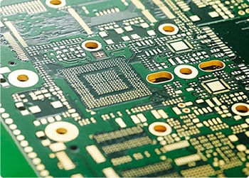
Most RF hardware designers face a familiar trade‑off: you need reliable high‑frequency performance, yet full Rogers‑only boards push material costs way up. A RO4350B + FR4 hybrid stack PCB solves this pain point well. This mixed‑lamination construction combines Rogers RO4350B high‑frequency substrate and standard FR4 dielectric within one single stack‑up. The idea is simple: deploy the costly high‑frequency material only where your RF signal traces actually run.
Rogers RO4350B delivers stable Dk values, low signal loss across microwave bands, and solid thermal stability. It performs consistently for 24 GHz radar units, wireless communication modules, and antenna feed circuits. Meanwhile, the FR4 portions handle power rails, large ground planes, and all low‑speed digital routing. You no longer waste premium high‑frequency laminate on board regions that never demand low‑loss electrical properties.
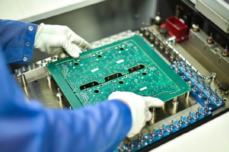
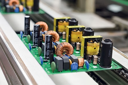
A well‑built RO4350B FR4 mixed laminate PCB preserves critical RF specifications. Fabricators use tightly controlled pressing cycles for RO4350B‑to‑FR4 bonding. Proper processing holds target impedance tolerances across the panel and prevents delamination during reflow soldering. Best of all, finished hybrid RO4350B FR4 boards work with standard SMT assembly workflows. Your contract assembler will not require special equipment or modified profiles for most production runs.
So where do the real savings kick in? 100 % Rogers RO4350B PCBs carry steep material overhead. When you confine RO4350B to RF‑critical signal layers and fill remaining layers with cost‑effective FR4 cores and prepregs, overall board pricing drops noticeably. Cost reduction becomes far more significant for large‑format multi‑layer designs, especially at medium‑to‑high production volumes.
That said, hybrid RO4350B FR4 mixed‑stack PCBs are not plug‑and‑drop. Thermal expansion mismatch between RO4350B and FR4 exists. Your PCB designer must prioritize stack‑up symmetry to minimise board warpage. Copper weight distribution and via architectures also deserve careful review. Partnering with an experienced PCB manufacturer familiar with RO4350B FR4 hybrid lamination keeps yield risks low.
This board type fits plenty of real‑life applications. RF sensor hardware, IoT wireless transceivers, small‑cell sub‑modules, and mixed‑signal high‑speed PCBs frequently select this stack‑up approach. It is not suitable for extreme high‑frequency applications where every single layer needs ultra‑low‑loss performance. Still, for most combined RF‑and‑digital circuits, it delivers acceptable electrical behaviour without the full Rogers price tag.
If your project calls for RF‑grade performance but you want to bring down overall PCB spend, RO4350B FR4 hybrid lamination PCB deserves serious consideration. Discuss your stack‑up options, impedance targets, and manufacturing tolerances with your PCB supplier early in the design cycle. Thoughtful pre‑production stack planning locks in consistent board quality and maximises achievable cost savings.
Rogers RO4350B Standard Material Specification Parameters
|
Parameter Category
|
Technical Item
|
Typical Value
|
Test Condition & Standard
|
|---|---|---|---|
|
Electrical Properties
|
Dielectric Constant (Dk)
|
3.48 ± 0.05
|
10GHz, IPC-TM-650
|
|
Dissipation Factor (Df)
|
0.0037
|
10GHz, low signal loss performance
|
|
|
Volume Resistivity
|
1.7×10¹⁰ MΩ·cm
|
Condition A, room temperature
|
|
|
Surface Resistivity
|
4.2×10⁹ MΩ
|
Standard atmospheric environment
|
|
|
Dielectric Breakdown Strength
|
500 V/mil
|
Insulation reliability test
|
|
|
Arc Resistance
|
125 sec
|
Anti-arc performance verification
|
|
|
Thermal Properties
|
Glass Transition Temperature (Tg)
|
>280°C
|
TMA test, IPC-TM-650
|
|
Thermal Decomposition Temperature (Td)
|
390°C
|
TGA thermal stability test
|
|
|
Z-axis CTE
|
32 ppm/°C
|
Low thermal expansion, improves PTH reliability
|
|
|
Thermal Conductivity
|
0.69 W/m·K
|
80°C working condition
|
|
|
Mechanical Properties
|
Flexural Strength
|
255 MPa
|
IPC-TM-650 standard
|
|
Tensile Strength (Y-direction)
|
175 MPa
|
ASTM D638, room temperature
|
|
|
Moisture Absorption
|
0.06%
|
50°C, 48h immersion test
|
|
|
Safety Grade
|
Flame Retardant Rating
|
UL 94 V-0
|
Industry standard fire resistance
|
|
Application Range
|
Working Frequency
|
500MHz – 77GHz
|
Suitable for full-band RF high-frequency circuits
|